I wanted to do something a little different with this post - and it'll probably get fairly technical, but it'll hopefully be interesting nonetheless. I've been fascinated with the maths and engineering behind games for almost as long as I can remember, and thought it might be interesting to condense some of that into a post (with pretty pictures) - if it's interesting I might do some more of these in the future. For now I'm going to explain the process of projection, with maybe a dash of texturing and lighting - there are actually some short-cuts and tricks used to speed the process up, but I'm mostly ignoring them for simplicity.
How it Works
One of the fundamental and vital things about drawing a 3D scene, is that almost everything can be approximated as a load of small, flat pieces (polygons) each joined at the edges, with a visible material applied to them. Computers generally use triangles, but you can also use quads or any n-gons if you feel so inclined. Each of the points which define the triangles can be expressed as a vector - 3 numbers, representing its X, Y and Z coordinates in space.
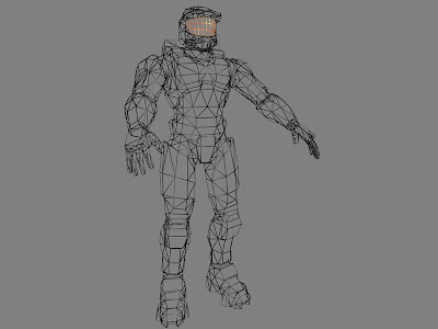 |
| Mostly triangles in there... |
Using some pretty self-explanatory maths, you can take a set of several different models, each positioned at different points in the world, and express them as a set of points (vertices) in the scene. So you now have a set of points in space. So what? They are pretty much useless, without some kind of viewing-point. The position and location of a camera in the world can also be expressed as a set of coordinates and a rotation - by using these bits of information, every point in the world can be shifted into a nice, simple set of values which are now oriented with respect to the camera - that is, the axes are aligned to the view-point and not the world or the objects. If you're confused, don't worry too much - essentially, what you now have is the points, but shifted so that the numbers now represent X, Y and Depth rather than the position in the world.
Unfortunately, our view on the world isn't quite as simple as this - if you imagine a simple cube, as described above, as seen face-on, each corner would be directly in front or behind of the rear face. In reality as we experience it, things which are further away appear smaller, so we shift points towards the centre of the screen depending on how deep they are. This now gives a pretty nice view of where each point on the model corresponds to on the screen - you can say that each point has been projected onto the 2D screen.
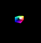
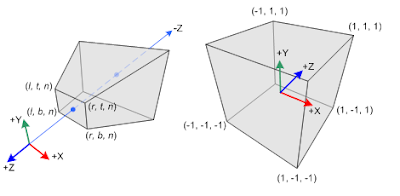 |
| The above diagrams represent perspective and orthographic space (perspective is on the left) - the space which is actually seen by the camera (the far end is the furthest object you can see - computer games limit how far you can look into the distance, sometimes with sneaky tricks) |
The initial projection I described is what's known as orthographic projection, which is useful if you need to work to a specific scale - for example, when designing a product with CAD. The depth-adjusted version is perspective projection, and is used when something needs to be displayed as it would be seen.
Once you have your points as they would be positioned on the screen, you can then draw in the triangles themselves. The easiest way would be to stretch a texture onto each triangle - though even this can have some quirks, which fall way beyond the scope of this blog post. A much more interesting and mathematical thing you can do is break each triangle into pixels and work out the colour of each - this is known as shading and can be done incredibly fast on modern graphics hardware.
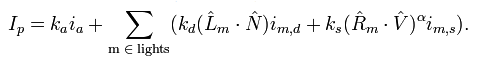
The Phong model of lighting (named after the first person to describe it, Bui Tuong Phong) can be used to shade a variety of material types very effectively - it's typically used for plastics or non-transparent liquids - Gels in Portal 2 for example. The principle is that the overall light reflected from a surface can be thought of as the sum of several different components, each of which is seen above.
The ambient (emissive) light is a term considered to always exist, but is often excluded because it is not strictly necessary. The diffuse (scattered) light is reflected in all roughly all directions by the material and does not depend on the viewing direction, only on the lighting direction. The specular (highlight) light is the intense highlight reflection you may see off shiny surfaces. Together, they can be summed up to give a pretty good representation of a material as a whole.
 |
| Restrain yourself, Jamie! |
The Ka, Kd, Ks and alpha are material constants - representing the material's ambient, diffuse, specular and "shininess" constants. Things with a hat on (^) are normalised vectors representing light and viewing directions, and the surface's normal. Ip is the output - the colour of a single pixel. This process is repeated for every single pixel of a scene (well, technically fragment - transparency can cause two or more fragments to be drawn for a single pixel).
 |
| Not personally a fan of the cave missions, but they definitely looked good. |
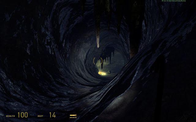
Of course, there are a huge number of other things you can (and indeed need to) do to make a realistic-looking scene which still performs well. For example, textures can be sampled to give much finer detail on items, and other shaders can be custom-written to handle reflective, refractive or translucent materials, metals, goo, or even supposedly simple things such as bumpy surfaces, as seen above. The cave's surfaces are actually flat - the surface shader is given a bump-map - a texture representing the height of a material rather than its colour. This can be used with a light vector (such as the torch) to give gorgeous, realistic-looking lighting effects, at much faster speeds.
Confused? Now remember that the computer handles about 100,000 vertices, depending on the game, and 1,000,000 pixels, 50 times a second, just in graphics calculations for a modern game.
Things I Haven't Mentioned
What about the other side of objects?
Sneaky trick with how you choose the triangles - you number the vertices in an anti-clockwise order around each polygon. When you're about to draw it, check if the order is still anticlockwise. If it is, you know it's facing you and should be drawn. If not, you're either looking at it sideways-on or from behind - which probably means you shouldn't be drawing it.
What about things behind you?
In the part where you move things with respect to the camera, things behind you end up getting a different sign on the depth to everything in front of you. You can just throw out any vertices with depth values below zero.
Anything else?
There's probably a solution or an explanation, but I'm really not going to pre-empt anything and everything you could ask. Ask in the comments, or wait for future installments, if this was actually interesting.
Yours geekily,
Charlie


